Thus, you have an ESP32 chip in the casing of an. But the best feature is that its 32 bits and dual core make it much more powerful. It has the 'face' of the Arduino Uno and is programmed with Arduino IDE. The World's Largest Arduino This is how I define this board that I’m introducing today, as it is basically a 'clone' of Arduino Uno.
It is similar to the Arduino Nano and Leonardo. It can be powered by the USB cable or by an external 9-volt battery, though it accepts voltages between 7 and 20 volts. The board has 14 digital I/O pins (six capable of PWM output), 6 analog I/O pins, and is programmable with the Arduino IDE (Integrated Development Environment), via a type B USB cable. The board is equipped with sets of digital and analog input/output (I/O) pins that may be interfaced to various expansion boards (shields) and other circuits.
There are 3 ways to power the arduino uno. 3 copi 4 reset 5 gnd 6 cipo sck oc2a copi pcint4 pcint5 pcint3 ft23rl icsp Arduino.Arduino uno rev3 schematic, n/a. Layout and production files for some versions of the hardware are also available.(Is it a Raspberry Pi 3B+/4B, Arduino UNO R3, Jetson Nano B01.
Arduino Uno Pinout Gnd Series Of USB
The ATmega328 on the board comes preprogrammed with a bootloader that allows uploading new code to it without the use of an external hardware programmer. The Uno board is the first in a series of USB-based Arduino boards it and version 1.0 of the Arduino IDE were the reference versions of Arduino, which have now evolved to newer releases. Circuit serial programming) header using arduino isp or similar Arduino Uno Rev3 R3 Opisanie Platy Drajvera Micropi from micro-pi.ru.The word " uno" means "one" in Italian and was chosen to mark the initial release of Arduino Software. Original arduino uno from italy.

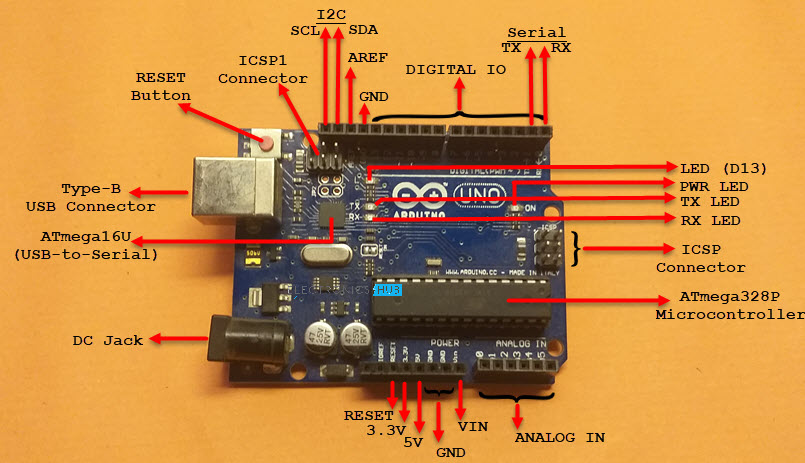
At that time, the students used a BASIC Stamp microcontroller, at a cost that was a considerable expense for many students. The Arduino project started at the Interaction Design Institute Ivrea (IDII) in Ivrea, Italy. Instead, it uses the Atmega16U2 (Atmega8U2 up to version R2) programmed as a USB-to-serial converter.
Arduino Uno Pinout Gnd Driver Chip And
Early arduino boards used the FTDI USB-to-serial driver chip and an ATmega168. But instead of continuing the work on Wiring, they forked the project and renamed it Arduino. In 2003, Massimo Banzi, with David Mellis, another IDII student, and David Cuartielles, added support for the cheaper ATmega8 microcontroller to Wiring. The Wiring platform consisted of a printed circuit board (PCB) with an ATmega168 microcontroller, an IDE based on Processing, and library functions to easily program the microcontroller. The project goal was to create simple, low-cost tools for creating digital projects by non-engineers.
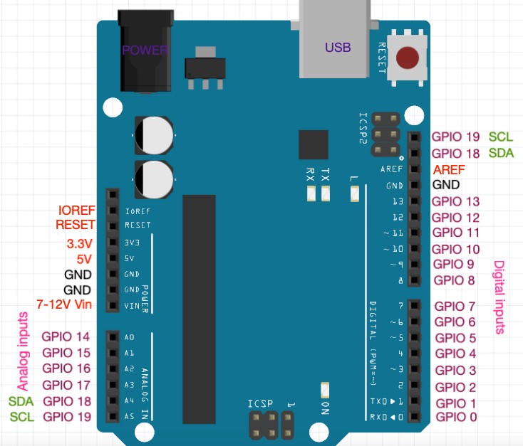
Power Sources: DC Power Jack & USB PortArduino UNO General pin functions Flash Memory: 32 KB of which 0.5 KB used by bootloader PWM Pins: 6 (Pin # 3, 5, 6, 9, 10 and 11) Digital I/O Pins: 14 (of which 6 can provide PWM output) Microcontroller: Microchip ATmega328P
5V: This pin outputs a regulated 5V from the regulator on the board. You can supply voltage through this pin, or, if supplying voltage via the power jack, access it through this pin. VIN: The input voltage to the Arduino/Genuino board when it is using an external power source (as opposed to 5 volts from the USB connection or other regulated power source). When the pin is high value, the LED is on, when the pin is low, it is off.
Reset: Typically used to add a reset button to shields that block the one on the board. A properly configured shield can read the IOREF pin voltage and select the appropriate power source, or enable voltage translators on the outputs to work with the 5V or 3.3V. IOREF: This pin on the Arduino/Genuino board provides the voltage reference with which the microcontroller operates. Maximum current draw is 50 mA. 3V3: A 3.3 volt supply generated by the on-board regulator. Supplying voltage via the 5V or 3.3V pins bypasses the regulator, and can damage the board.
In addition, some pins have specialized functions: By default, they measure from ground to 5 volts, though it is possible to change the upper end of the range using the AREF pin and the analogReference() function. The Uno has 6 analog inputs, labeled A0 through A5 each provides 10 bits of resolution (i.e. A maximum of 40mA must not be exceeded on any I/O pin to avoid permanent damage to the microcontroller. Each pin can provide or receive 20 mA as the recommended operating condition and has an internal pull-up resistor (disconnected by default) of 20-50K ohm.

AREF (analog reference): Reference voltage for the analog inputs. Support TWI communication using the Wire library. TWI (two-wire interface) / I☬: pin SDA (A4) and pin SCL (A5). These pins support SPI communication using the SPI library. SPI (Serial Peripheral Interface): pins 10 (SS), 11 (MOSI), 12 (MISO), and 13 (SCK).

Automatic (software) reset Rather than requiring a physical press of the reset button before an upload, the Arduino/Genuino Uno board is designed in a way that allows it to be reset by software running on a connected computer. A SoftwareSerial library allows serial communication on any of the Uno's digital pins. The RX and TX LEDs on the board will flash when data is being transmitted via the USB-to-serial chip and USB connection to the computer (but not for serial communication on pins 0 and 1).
When the Uno is connected to a computer running Mac OS X or Linux, it resets each time a connection is made to it from software (via USB). This setup has other implications. When this line is asserted (taken low), the reset line drops long enough to reset the chip.
Anything besides an upload of new code), it will intercept the first few bytes of data sent to the board after a connection is opened. While it is programmed to ignore malformed data (i.e.


 0 kommentar(er)
